Understanding three phase power
Migration to Hugo
I have migrated this 14-year-old blog from a dynamic WordPress (based on WordPress) to a static website (based on Hugo). It was a pretty lengthy process even when I had scripts converting the WordPress XML export into markdown files.
Why a static site?
This gives a few advantages like:
- Must faster rendering as all the pages are generated well in advance & pushed to the server
- Better security (as the backend is not at all exposed unlike WordPress where backend admin portal was visible & behind an authenticated URL)
- Easy to distribute and put behind CDN
- Easy to type posts as now it’s just markdown
I haven’t finalised the hosting location for this newer site. For now, it’s on Google Cloud firebase but I am still just playing with the options. If I get some free time, I might just tweak my PowerDNS setup to start using GeoIP data for the request and serve the local server in a given country. That way I can host the website in India, Europe and US and let authoritative DNS steer the traffic. More on this later!
Most things are finished except a few things like RSS exports to email automatically etc. Planning to do that soon once I get some time. Do share feedback on this blog and any bugs. This was 200+ post-migration and a pretty tiring process with semi-automation. This is going to be a busy week!
Coming to the topic of this specific post - “Understanding three phase power”…
Background
Over time electrical load at our home has increased and that has caused some trouble couple of times with the fuses. Thus we went for an increase in electric load from the local grid and were told to switch to three phase power supply. Basically in Haryana load of 5KW or above has to be delivered over three phases. I heard of three phases and probably most of the people have from their class 12th physics or first-year Electrical Engineering course at college but honestly, I barely remember the concept. That’s a standard problem. Most of us barely learn or remember any concepts from formal education and it’s hard to get anything done about it. The computer, IT world has moved on with its own set of courses and specialisations and I would guess other domains would have done as well.
To understand three-phase power, why it’s not just 3 x single phase capacity, why over 5KW is not delivered over a single phase, what is neutral in modern AC supply etc, one needs to go back to the basics of electricity.
Fundamental electrical concepts
- Current: It’s measured in Amperes & means 6.241509074×10¹⁸ electrons worth of charge moving per second
- Voltage: Measured in volts and represents the difference in potential between two given points
- Resistance: It’s measured in Ohms and is a measure of opposition to the flow of electric current. Its ratio of Voltage (V) / Current (I)
- Power: Measured in Watts and is a product of Voltage (V) x Current (I)
- Alternating Current: AC power/case where current (I) is alternating its path as defined by the frequency
- Frequency of AC: This is defined in Hz and tells how many times current (I) is changing its path in a given second. E.g in India supply is 50Hz meaning a change in the flow direction of current (I) 50 times every second. That would also explain your reason for “on/off” in electric shock from the power outlet. I guess most readers would have felt electric shock a few times in their lifetime. :)
Now electrical grids are essentially based on the trade-off between two key components:
- Safety of the system
- Economics
In many cases, both of these are against each other and hence the trade-off. We can have an extremely safe system which may not be economically feasible OR we can have an extremely cheap system that might be quite dangerous to operate. Thus what we eventually have is something in between & engineering wise it’s amazing. The basic operation which grids are supposed to do is to carry generated power from the generation plants all the way to the end user.
Understanding technical losses
The most fundamental loss happens because of resistance in the wires. Resistance leads to “resisting” the electrical flow and hence turns part of the energy into heat. This leads to energy wastage and degradation of transport material (wire, cables, connectors etc). Resistance can be kept as low as possible to a fixed extent as it’s often a property of the used material. In other terms, there’s a limit to reducing the resistance in a system beyond a point.
Thus the attributes grid operators can tweak are:
- Current (I)
- Voltage (V)
- Other smart tricks (multiple phases instead of single phase, more on this a min)
If power is increased, resistance increases significantly (Ohms law), plus we would need thick conductors. If voltage is increased, the impact of resistance is lower and one can use thinner conductors but high voltage is hard to handle safety-wise. Beyond a few thousand volts there is a problem with the electrical arc. When the potential difference is very high, even the moist air can conduct and thus conductors have to be placed far apart which is not practical for domestic usage. We cannot maintain a few meters of the gap between the phase & neutral of the home electrical socket or even domestic distribution transformers & wiring.
This brings the design of step-up & step-down transformers. Power is typically generated in a few thousand volts (varies depending on turbine but can be 1000 to 20,000 V) and then is stepped up a few 100,000 Volts and is transported at longer distances. Next, it’s stepped down to 33KV sub-stations, next further to 11KV feeders. typically 11KV feeders feed individual street transformers. It’s 11KV / 11,000 V at one end on the primary wiring and 230V on the secondary wiring. In a simple single-phase setup (which it is not but for sake of calculation) - 11000V is 47.82 times more than 230V. Thus voltage is 47 times more and hence current can be 47 times less for the same amount of power. Thus if a transformer is serving say 20 homes, each with 2KW of load, it would be 40KW worth of power during peak and at 230V it would be 40,000/230 = 173 Amps which is very high. Even a thick 16mm wire can carry up to 70amps. But at 11000V that’s just 40000/11000 = 3.6Amps (a bit more due to losses at the transformer). 3.6Amps can be carried over on a really thin wire. Even a 1mm wire can do!
So that’s about the need for step-up and step-down transformers. Next comes the idea of phase.
Sine wave power
Modern power systems generate sine wave current i.e if we plot the waveform it looks like a mathematical sine wave.
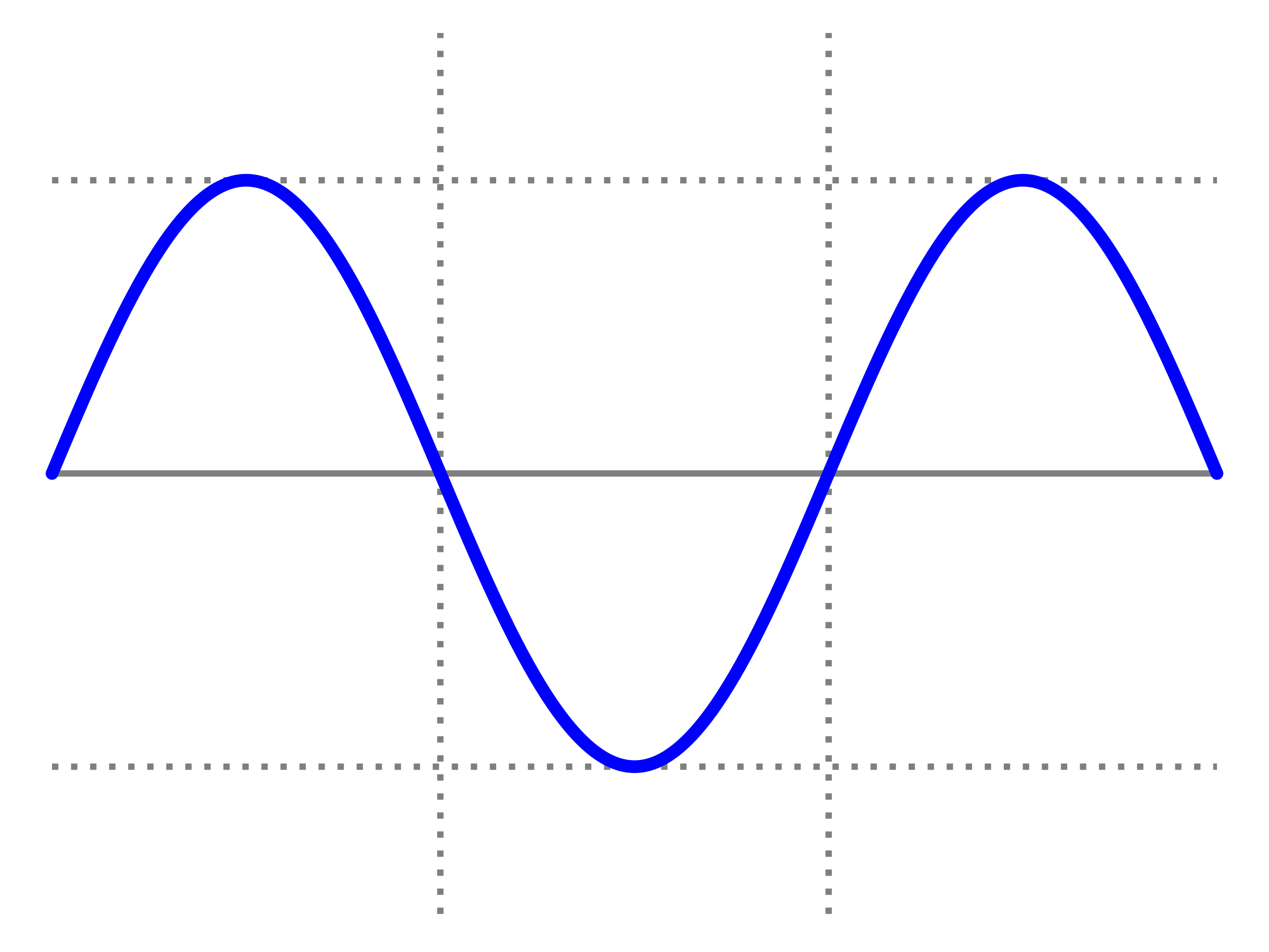
Now instead of having a single coil next to a rotating magnet which is being rotated via steam or wind or water, we can have three coils at 120 degrees phase shifted.
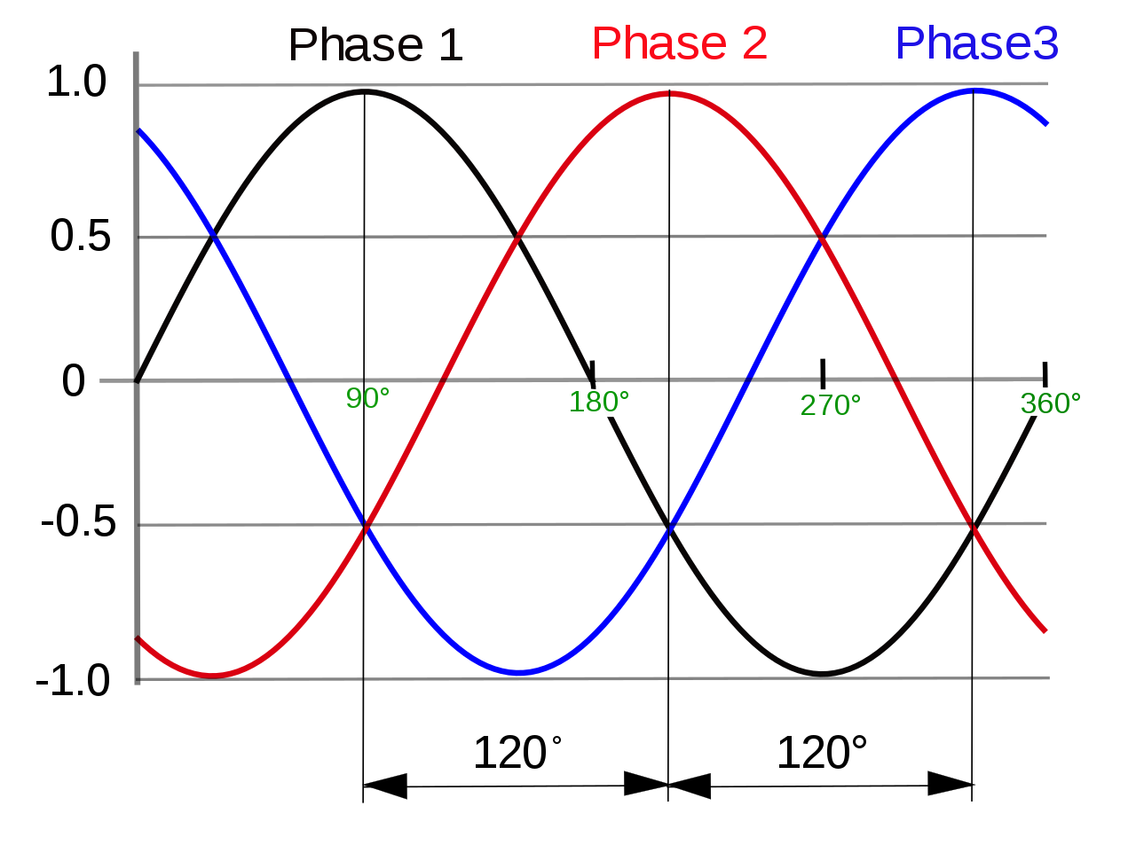
This gives us three phases and as the magnet rotates, it generates three phases of power which if plotted would look something like this:
A few quick points here:
- At 50Hz, these phases are changing / alternating 50 times a second
- One end of these three coils is connected together i.e shorted (to form a neutral point of a star topology) and another end of each coil gives a phase (red, yellow and blue)
- Due to 120-degree phase difference, when the voltage in one phase reaches its peak, the other two are at 1/3rd with one in decreasing stage and the other in the increasing stage
- In a perfectly balanced load across all three phases, the returning current via neutral cancels each other and there is zero current in the neutral!
- Because of zero current in neutral, in a balanced load scenario, no neutral is required and the grid at large does not have a neutral until the last mile, the final delivery transformer
This may bring questions on how in the world load is balanced between the three phases.
Essentially grid design ensures that load is as spread out as possible across all three phases and for a small % of unbalanced load, it’s managed through neutral at the last few meters of the delivery point. More on this in detail in the next section.
So why three phases instead of a single phase?
That’s simply because in a single phase neutral is needed, in three phases for balanced load neutral is not needed thus instead of 2 conductors (phase and neutral), three-phase needs 3 conductors (phase 1, phase 2, phase 3) and for 1.5 times more conductor (3 instead of 2) one can carry 3 times more power. One can, in theory, have 6 or 9 or even 12 phases but beyond three phases it has proven to be not so economical due to extra cabling, connectors, circuit breakers and more.
Unbalanced load | Neutral | Single phase | Three phase domestic setup
Typically for transformers on the street, primary winding connects in delta topology i.e it only gets three phases - R, Y and B while the secondary winding (doing voltage step down) connects in a star topology.
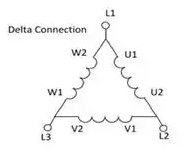
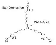
This is done because phases cannot be perfectly balanced & thus if secondary winding also is connected in delta topology, there won’t be a way to balance the phases. For single phase connection if all the houses (load) are spread evening, still someone would be using more power, some would be using less power and hence the imbalance. The neutral star topology would be the current back and is often grounded at the transformer. This ensures that despite minor wastage, the neutral point and thus all three phases are balanced even in case of an unbalanced load. The more the phases are balanced, the less is the current returning to neutral. If this is not done, voltage levels won’t maintain and typically phases with higher load will have lower voltage and vice versa. If all connections are three phases and all connected electrical load is three phases and is perfectly spread out, neutral is not even needed at the last mile transformer.
Why is single-phase power even provided?
This goes back to the economical reason. A large number of users do not need more than 2-3KW at peak and hence they can be served using a single phase and neutral. Only two conductors, two fuses, simpler, two circuit breakers (MCB), overall a cheaper setup.
How much max power can three phases do?
Well, quite a lot. That’s because now typical home single phase load can be spread between three pairs of phase 1 - neutral, phase 2 - neutral and phase 3 - neutral. The voltage between all these points (line voltage) is usual 230V. But the voltage between the phases (phase voltage) is 440V. Thus for higher loads, one can use 440V between two given phases and that’s around 2x more volts, thus 1/2 current for the same power. Thus for same-sized conductors, power can be increased significantly. Though 440V is often used by industrial gear with native three-phase support. When we were getting the connection, we were offered to put 16mm wire for up to 20KW load though we opted for 10mm wire for 10KW of max possible load.
Why only 4 wires i.e 3 phase and one neutral instead of 6 wires i.e 3 phase and 3 neutral?
This goes back to the concept of a 120-degree phase-shifted supply. Thus returning current cancels each other and in a perfectly balanced load, there is zero return on the neutral. Thus if one has a 10Amp load on phase 1 (red), the return via neutral is 10Amps. If the load on phase 1 (red) and phase (yellow) is 10Amps each, the return via neutral is just 10Amps and not 20Amps. Furthermore if the load on all three phases i.e red, yellow and blue is 10Amps each, the return will cancel each other and will be zero. Thus 3 x neutral wire is not needed.
The video embedded below explains it beautifully with an identical heater load across all three phases.
So no neutral wiring at all for identical spread out the load, how the circuit complete?
As I was reading this topic, I found this confusing, If load is balanced, we remove neutral, how the circuit will complete?
Short answer: It won’t and the device won’t function. One side of all three identical loads connects to each phase and another end has to be shorted together. Else returning current won’t meet at a common point to cancel each other. For devices supporting three-phase input natively like three-phase motors, the internal circuitry takes care of it.
US & Canada 120V setup
US and Canada are one of the very few countries which use 120V. In fact they used to use 110V and it was switched up to 120V sometimes in the 1980s. Thus for the same set of typical loads i.e bulbs, fans, laptops, mobile chargers etc internal wiring carries 2x more current at roughly 1/2 voltage. To deal with a massively high load, most of the homes in the US and Canada have a “split phase” setup where two phases are sent along with a neutral. These phases are 180-degree phase shifted and each of them gives 120V with neutral but the voltage between these split phases is 208V (not 2x but close to 2x) which helps in reducing current (I) on the lines where power consumption is high. Thus most of the heavy ovens, air conditioners, and washing machines in the US/Canada are connected between the phases instead of phase & neutral. More about this in a detailed Wikipedia article here. US / Canada are a bit unusual in this way as besides operating at a lower voltage (at one of the places with very high per capita consumption), they also typically do not offer three-phase power to domestic users. In Europe, India and many other countries in Asia, three-phase power is quite commonly available. It probably has to do with large legacy installations Vs late mover advantage.
There are many other fields where India moved later and thus has the advantage of better technology like a lot of fibre to the home on fixed line connections, more mobile phones than fixed lines, way more UPI instead of plastic cards, better airports etc.
EVs and fast charging
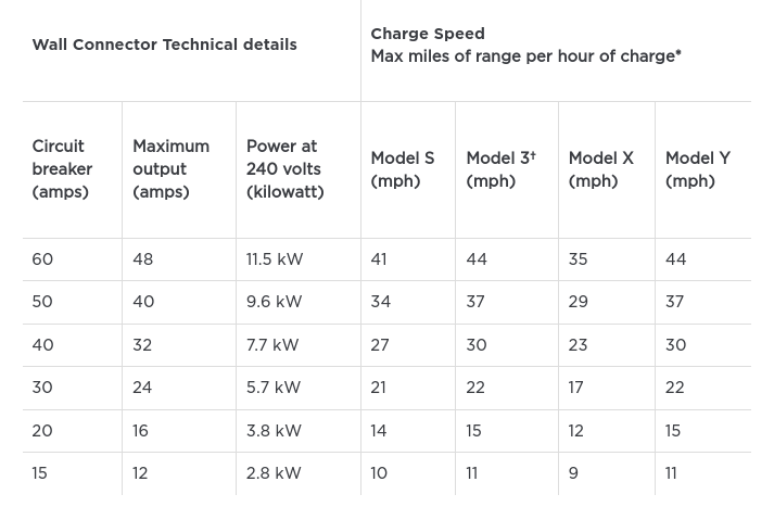
While many homes across the world did not need over 3-4KW of power so far, electric vehicles are very likely going to change that. Typical home charging of EVs (take the case of market leader Tesla) can take a max of 11.5KW. Here are a table mapping power, current and charge miles per hour from the Tesla website.
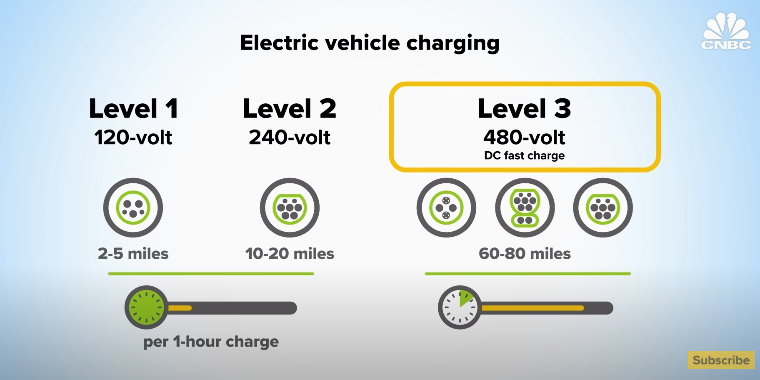
Furthermore, this CNBC report points to level3 chargers which can do 60-80 miles per 20mins charge at 480V.
All this points to the upcoming higher load we can expect from domestic users.
The electrical grid is fascinating! :-)