Understanding earthing/grounding
In Aug of this year, I posted about three-phase power. Subsequently, I had a discussion with a friend from Delhi about bonding neutral with earth/ground at the distribution panel. He has a commercial load of 20KW delivered via three phases and his electrician advised him to bond neutral with the ground. We both were curious whether it was technically correct or not. Taking a break from network engineering, here goes a post about it.
Fear of neutral disconnect in a three-phase system
As mentioned in my previous post, in a perfectly balanced three-phase system, currents cancel each other on return and thus common neutral point has zero current hence neutral actually can be disconnected between the common shorted point and distribution transformer secondary coil (connected in star). But a typical three-phase setup with a different set of loads spread across each phase would never be balanced. Now if accidentally neutral is disconnected from the transformer (say the cable just broke down), we will have a load attached in series between different phases and that can have a phase voltage of 415V going in series across these devices designed for 230V. That would just burn the primary point where such high voltage would hit.
So it could be the case that the local electrician would have thought to ground neutral at the panel to save from possible damage in case of neutral disconnect. But again is that technically correct?
US/Canadian system
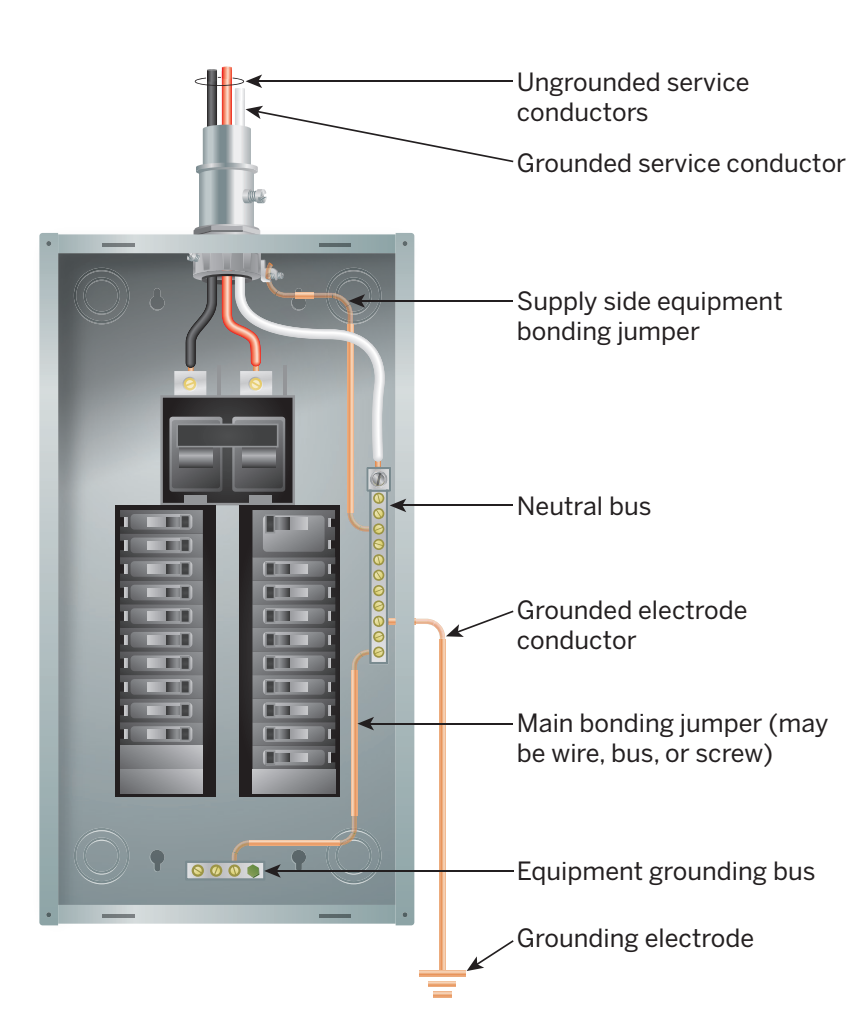
If you search for a connection of neutral with earth, a lot of material will appear from North America, “earth” would be replaced by “ground” and there will be a constant recommendation that indeed neutral bar at the distribution panel should be connected to “ground bar”. It’s part of the US National Electrical Code (NEC) Article 250.
This is something we do not see in India. This is because there are different methods to do electrical earthing with their own set of advantages and disadvantages. Before understanding standards, it’s important to first understand what we are trying to achieve here. So touching some fundamentals quickly. This will help in understanding what the design is trying to protect against!
Re-visiting fundamentals
-
Voltages vary by country. In India, at minimum, it’s 11KV line (11000) volts feeding these distribution transformers. These are typically served by 33KV, 66KV and so on.
-
At the distribution transformer, there are two windings - primary and secondary. Primary winding connects to the 11KV coming from the upstream and secondary connects to the end user load. Now primary winding is connected in a delta where coils are connected to form a triangle and each end connects to each of the phases. Secondary connects in star topology where one leg of each coil is shorted and the other end gives each phase.
-
Now by nature load across end user’s residential areas cannot be perfectly balanced across all three phases and hence shorted point of the coil i.e cannot be zero. This shorted point gives us a “neutral” conductor which does two important jobs: 1) It gets the non-cancelled, extra current back to the transformer/source and 2) It helps to complete the circuit for single phase loads.
-
Current flows in a “close” circuit and if that circuit is “opened”, electrons try to find a way to return to the source. The source for residential areas is transformer coils.
-
There can be many failures in such a system but broadly two are the dangerous ones - 1) In an end-user device (like say washing machine) phase starts touching the body of the machine and thus the body reaches the dangerous voltage of 220V 2) A vehicle strikes the pole and either phase together or phase & neutral are shorted.
-
We get an electric shock when we come in between the flow of electricity and a current as low as 30mA is high enough to cause respiratory paralysis and currents above 75mA can kill.
-
Human body’s resistance varies (dry or wet, touching ground or not, part of body nails Vs skin Vs tongue etc). Typically current 1.1mA current can give sensation, 10mA can get a person locked with muscles not moving and 65mA can stop heart functioning. By Ohms law, V = IR, thus to pass 0.065A of current across a body with 1500Ohm resistance, the voltage will be = 0.065*1500 = 97V. Thus the potential difference of 97V or even lower than that with sufficient current (above 10mA) is fatal to human life.
-
Both current and voltage are important in the context of electric shock. A lower voltage won’t be able to push enough current due to human body resistance but the higher voltage doesn’t guarantee electrocution if the current is limited below 1mA. In an electrical grid however current is very high and hence coming in between a high voltage circuit i.e body coming “in-between” will always give a severe if not fatal shock.
-
A circuit breaker / MCB can break a circuit if excessive amounts of current flow through it. This can be due to excessive load and also due to shorting i.e when phase & neutral are shorted and excessively high amounts of current flow due to a low resistance path.
Types of earthing
With that understanding in mind, here are the different types of earthing/grounding methods used across the world. Wikipedia explains it in detail here. The circuit diagram source is also Wikipedia.
- TN-S
- TN-C
- TN-C-S
- TT
- IT
These categories are using IEC (International Electrotechnical Commission) terminology where the first letter indicates a connection between the source (e.g transformer) & earth, second indicates a connection between an electrical appliance (e.g washing machine) and the earth. “T” means earth (taken from Latin terra), I means no connection, and N means Neutral conductor. This can be confusing at first look but is easier to understand when one starts looking at each system.
1. TN-S

In this setup source i.e transformer is grounded, the neutral at the transformer is also grounded and the grid operator provides the earth from the transformer. Thus single-phase supply in this case has live, neutral and earth (3 cables) from the transformer. And three phase has three live phases (L1, L2, L3), Neutral and earth i.e 5 cables. Note: earthing conductor is referred to as PE i.e “Protective Earth”.
In this case, if live touches the body of the appliance, the connection will be shorted immediately resulting in a very high current flow for a fraction of a second and the circuit breaker (MCB) will trigger to disconnect. If the neutral conductor is broken in this case, nothing fatal would happen. (This may seem weird to read but read on the other methods and you will see that is not the case with all methods).
This is one of the most expensive methods of earthing due to the use of a dedicated conductor from the transformer to each drop point.
2. TN-C

In this case, also transformer & neutral point at the transformer is grounded but instead of carrying neutral (N) & earth (PE) separately, they are carried together on a single conductor and it is referred to as PEN i.e Protective Earth Neutral. Thus effectively single conductor is used here as a return path for the load (neutral) and also to cause a short circuit triggered circuit breakers in event of a fault in a device where the live wire touches the body.
In the TN-C setup, if live wire touches the body, a short circuit will result in massive flow triggered by the circuit breakers and hence saving an individual from coming in contact with high voltage. However, if the PEN conductor is accidentally disconnected, the body of the appliances will reach a dangerous line voltage and if anyone comes in contact with it, the current will flow from the live phase to the human to the ground and back to the transformer giving seveare shock. Hence this method is dangerous if instead of an appliance, the grid neutral cum earth (PEN) conductor is damaged/disconnected.
3. TN-C-S
Now, this is an interesting system & a mix of both TN-S and TN-C in a clever way. Here source transformer is grounded, neutral is grounded but only neutral is carried to the drop point (like TN-C). At the entry point in the property, local grounding is done (though optional in certain countries) and neutral is grounded again along with earthing cable. Thus neutral is grounded at the transformer as well as the consumer’s drop panel. But separate beyond that. It is also called PME i.e Protective Multiple Earthing for this reason.
In this setup, if live touches the appliance body, a higher amount of current will flow from the live wire to the earth conductor (PE) until the panel and will return to the transformer (lowest resistance path) via neutral. If for some reason neutral disconnects between a drop point and the source, the ground will give an alternate path for current to return instead of buildup on the appliance body. This system is used in the US domestic grounding and is referred to as Multi-grounded Neutral. If neutral is not grounded in this setup, it can have dangerous behaviour during the neutral disconnect condition.
4. TT

In the case of TT, the source is grounded, neutral is grounded and only neutral is carried to the drop point. PE and N are not combined here. At the drop point with the subscriber, there is a separate grounding electrode (similar to TN-C-S) but that grounding is not connected to the neutral at the subscriber drop. If live wire touches the appliance body in this case, the current reaches the main panel via PE conductor and goes to ground and returns the source via ground. The disadvantage here is the high impedance of the ground would result in a much lower flow of current compared to other methods. Any sort of damage to grid distribution cables i.e neutral disconnecting, live shorting neutral etc has no effect here since earthing (PE) conductor is all the way separate and thus will not energise any appliance body. This design is popular in Indian domestic earthing.
5. IT
In the case of IT, nothing connects to earth and earth is not supposed to act as a return path. So in a perfect world, if an IT system is used, we do not need grounding at all and we won’t get shocked if we touch live wire as our body will not complete the circuit. Isn’t that great? This would make one wonder why do earthing at all and isn’t a non-earthing system IT is safest?
Well no, because of three key reasons.
-
Humans can touch high voltage in the IT system and there won’t be current flow as long as there is a low-impedance circuit present. Any nearby insulation fault in the area will turn IT into TN. And worst in a perfect IT system with no insulation, no one will notice any dangerous voltage until the insulation fault.
-
Transformers & other equipment has to be grounded to keep them safe from lightning strike where the earth completes the circuit and a high amount of electrons try to find their way to the earth and fry everything in between if proper grounding is not manained. As soon as grounding is done to save the system from lightning, an alternate path via earth exists and has to be taken care of with other non-TT mechanisms to detect the fault and open a circuit breaker.
-
If a high voltage line falls on low voltage, in absence of earth, a fault will result in massive voltage on the low voltage conductor. While the case of a grounded setup, this will not happen.
Thus on the question of grounding neural at home - it is not done in the TT method and if done, it will convert into TN-C-S but then standards have to be kept in mind because when we combine earth (PE) with neutral (N) i.e PEN conductor, it can bring full line voltage to an electrical appliance body in event of discontinuity in PEN conductor.
Neutral grounding for generators
Diesel generators are supposed to have neutral grounding done. This again ensures the system does not turn into a partial IT system. Indian electricity regulations CES rule 41, sub-clause 13 states:
neutral point of every generator and transformer shall be earthed by connecting it to the earthing system by not less than two separate and distinct connections
This ensures of return path in event of a fault in the device with phase shorting the neutral. One can refer to the CEA safety regulations 2010 here.
RCCB - Residual Current Circuit Breaker
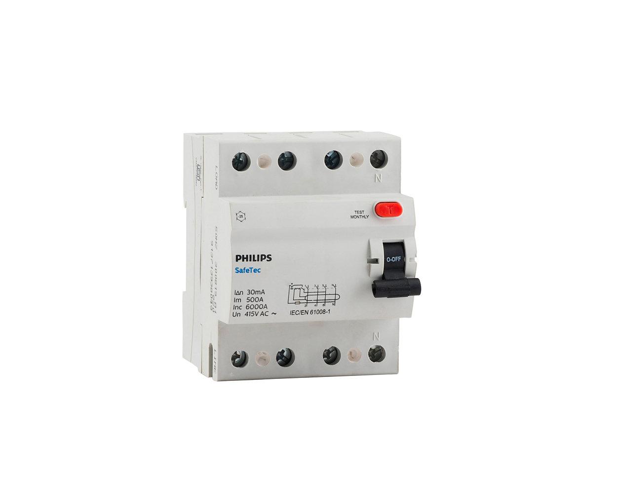
While earthing gives some protection, modern RCCBs offer another layer of fine protection against electrical shock. These devices are based on Kirchhoff’s law and essentially ensure that the current flow between phase and neutral is symmetric. Usually, in the case of an electric shock, the return current is not via neutral (unless a person is touching both live & neutral together!). The return current from the body is via the ground. RCCBs look for conditions where the return current is lower than the incoming current and trip the circuit within 25 to 40 milliseconds to prevent severe shock. They are quite sensitive to “leakage” via ground and can detect as low as 5 to 30mA of leakage and disconnect. In the case of three phase concept is similar but instead of measuring on neutral, it would look for a nonzero-sum of all three phases and neutral.
Disclaimer: I have a limited understanding of these concepts. Do not make a plan based on this post but consult a professional. There are many conditions in the electric code which must be followed when making changes.